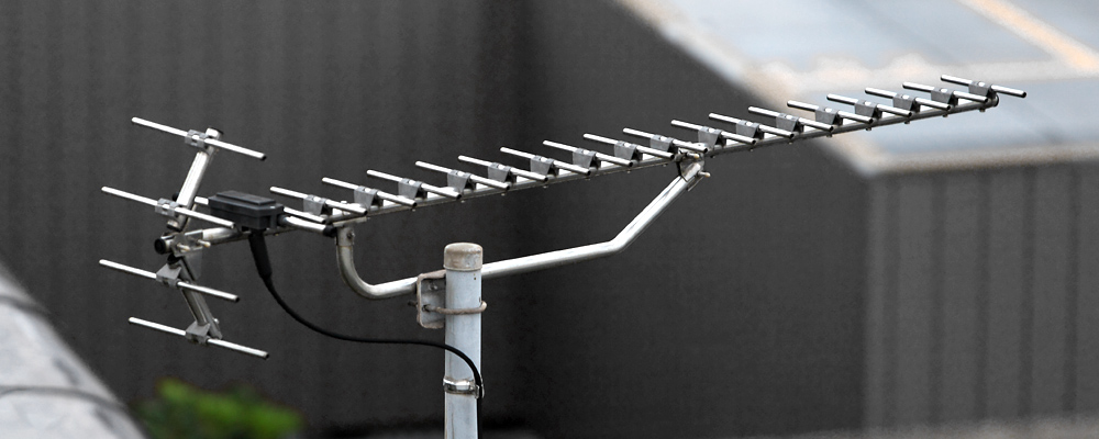
Corner Reflector
Reflector Antennas Microwave UHF Directional
A dipole in front of a V-shaped reflector for moderate, simple gain.
- Band
- UHF to SHF
- Gain
- ~10-15 dBi
- Polarization
- Linear (driven element)
Photos
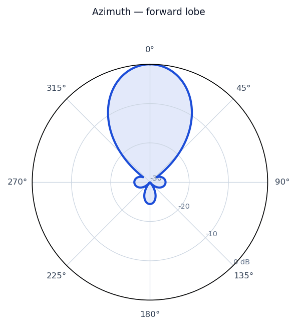
Radiation / wave patterns
New to these diagrams? How to read a radiation pattern →
How & why it works
A corner reflector places a driven dipole in front of two flat conducting panels joined at an angle (typically 90 degrees). Image theory shows the corner produces multiple in-phase reflected images of the dipole, which combine to push energy forward and substantially raise gain over a plain dipole. It is simpler and more broadband than a dish and is effective from UHF through low microwave frequencies.
Real-world uses
UHF point-to-point links, radar reflectors, and base-station sector antennas.