Half-Wave Dipole
Wire Antennas Beginner HF 🔧 Buildable at home
The simplest resonant antenna: two straight conductors fed at the center.
- Band
- HF to UHF (scaled to band)
- Gain
- ~2.15 dBi
- Polarization
- Linear (orientation of the elements)
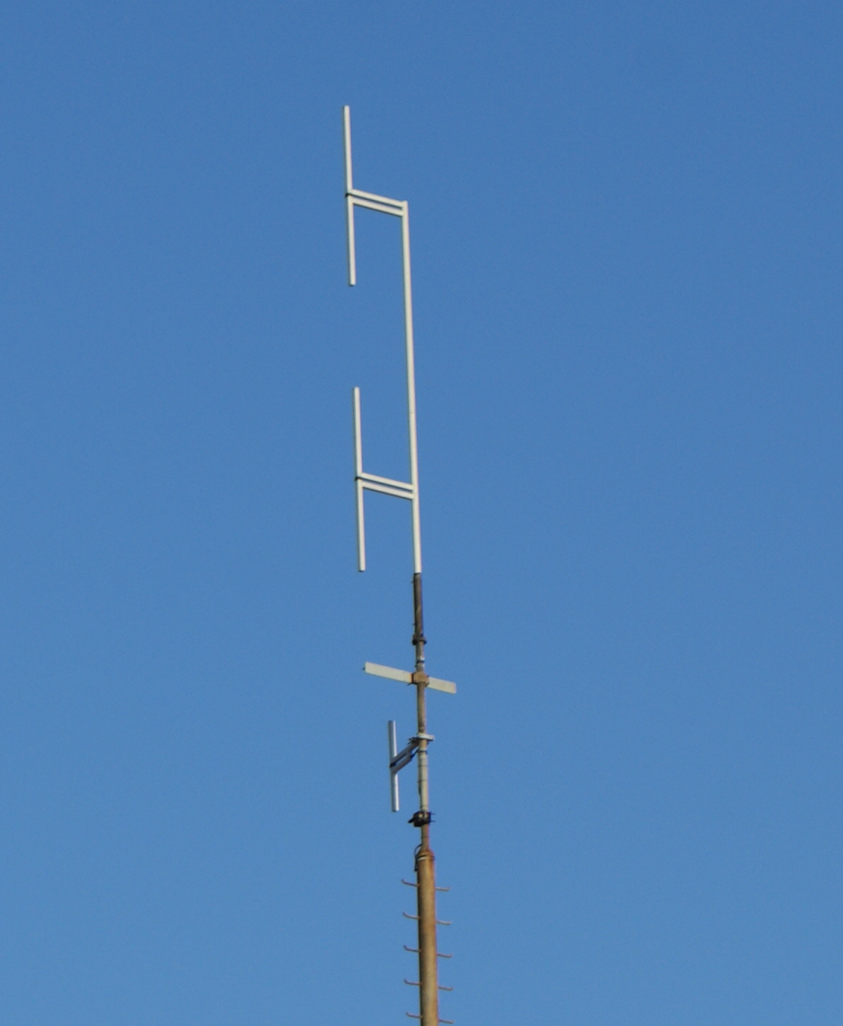
Photos
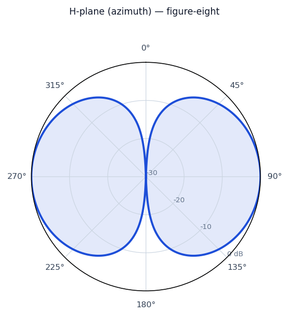
Radiation / wave patterns
New to these diagrams? How to read a radiation pattern →
How & why it works
A half-wave dipole is a conductor cut to roughly half the wavelength of the signal, split in the middle where the feedline connects. At resonance the standing-wave current is maximum at the center and the voltage is maximum at the ends, giving a feedpoint impedance near 73 ohms that matches common coax reasonably well. It is the reference against which other antennas' gain is often measured (dBd).
Real-world uses
Amateur radio HF/VHF, FM broadcast receive, and as a building block for more complex arrays such as the Yagi-Uda.
Make one at home
A practical starting point — always trim and check SWR for your exact frequency.
See the finished antenna pictured above ↑.
A half-wave dipole is the classic first build — two wires and a feedpoint.
You’ll need
- Insulated stranded wire (about 1.5 mm² / 14–16 AWG)
- A centre insulator (or a plastic block) and two end insulators
- 50-ohm coax + a connector; ideally a 1:1 current balun/choke
- Rope to support the ends
Cut to length
Total length in metres ≈ 143 ÷ frequency (MHz); each leg is half that. For 7.1 MHz that’s ~20.1 m total, ~10.06 m per leg. Cut each leg a little long (a few %) so you can trim.
Build
- Attach a leg to each side of the centre insulator.
- Connect coax centre to one leg, braid to the other (via the balun/choke to keep RF off the feedline).
- Fix end insulators and hang it as high and flat as you can.
Tune
Measure SWR, find the lowest point, and trim both ends equally a few cm at a time to move it up in frequency (or add wire to go down).
Safety
- Keep antennas well clear of power lines — never put one where it could fall onto or contact mains wiring.
- Don’t transmit while anyone is close to the antenna; mind RF-exposure limits and your local licensing rules.
- Ground masts and use coax surge protection where appropriate.
- Cutting/soldering: eye protection and a ventilated space.