Folded Dipole
Wire Antennas HF VHF 🔧 Buildable at home
A dipole made from a closed loop of two parallel conductors for higher impedance and bandwidth.
- Band
- HF to UHF
- Gain
- ~2.15 dBi
- Polarization
- Linear (element orientation)
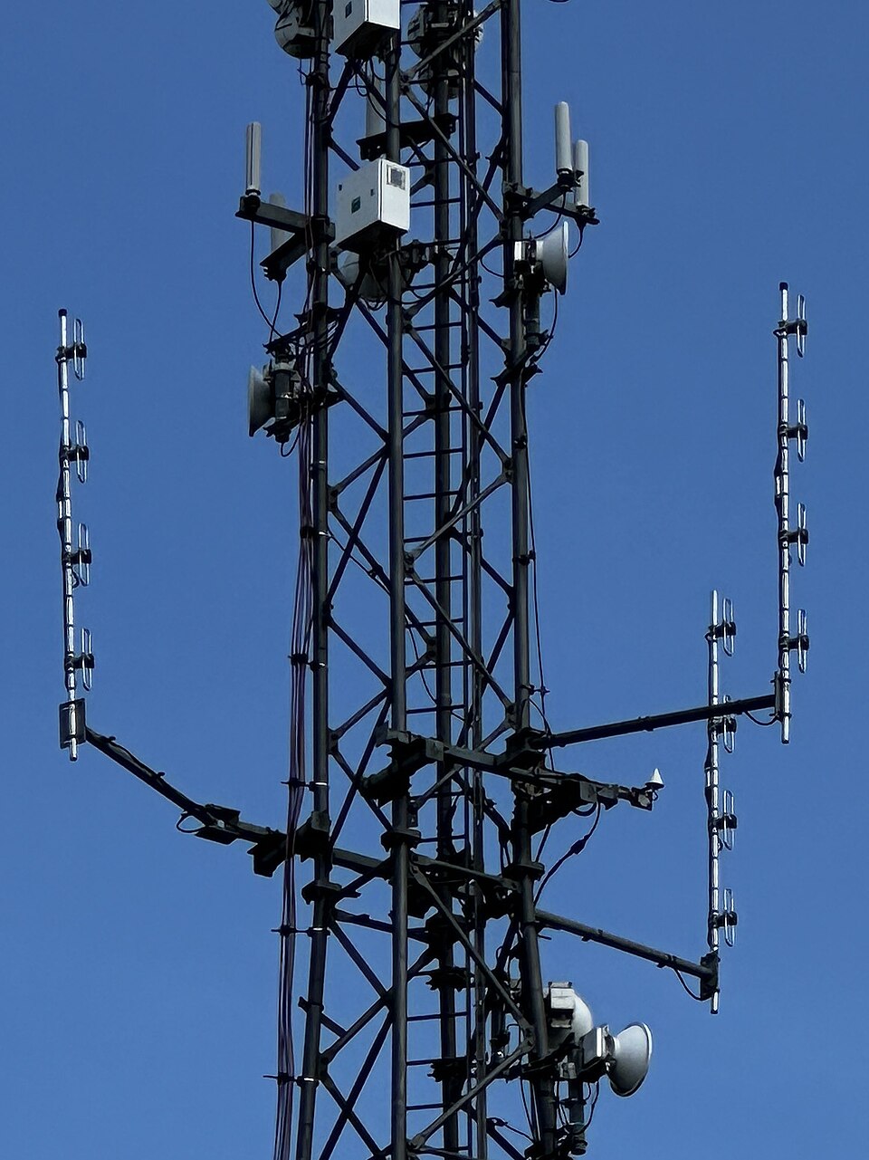
Photos
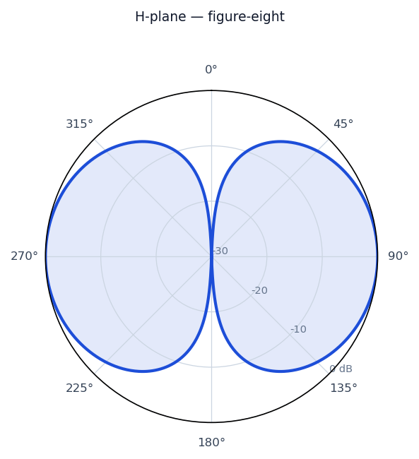
Radiation / wave patterns
New to these diagrams? How to read a radiation pattern →
How & why it works
A folded dipole joins two closely spaced half-wave conductors at the ends to form a thin loop, fed at the middle of one side. The current splits between the two conductors, which raises the feedpoint impedance to about 300 ohms—a four-fold step-up over a plain dipole—making it a natural match for 300-ohm twin-lead and the driven element of many Yagis. The two-wire structure also widens the usable bandwidth and adds mechanical robustness.
Real-world uses
FM/TV receive antennas, Yagi driven elements, and 300-ohm twin-lead installations.
Make one at home
A practical starting point — always trim and check SWR for your exact frequency.
See the finished antenna pictured above ↑.
A folded dipole is a dipole made from a loop of wire — more bandwidth and a handy 300-ohm feed.
You’ll need
- 300-ohm TV twin-lead (the simplest route) or two parallel wires with spacers
- A 4:1 balun (300 Ω → 75 Ω) or 6:1 (300 Ω → 50 Ω) to feed with coax
Build
- Cut a length of twin-lead = 143 ÷ f(MHz) metres.
- At the two far ends, twist and solder the two conductors together (closing the loop).
- At the centre of one conductor, cut it and connect the balun there; the other conductor stays continuous.
Tune
Trim both ends equally for lowest SWR. The folded design is broad, so it’s forgiving.
Safety
- Keep antennas well clear of power lines — never put one where it could fall onto or contact mains wiring.
- Don’t transmit while anyone is close to the antenna; mind RF-exposure limits and your local licensing rules.
- Ground masts and use coax surge protection where appropriate.
- Cutting/soldering: eye protection and a ventilated space.