ILS Glideslope Antenna
Aviation & Air-Traffic-Control Antennas Navigation UHF Aviation
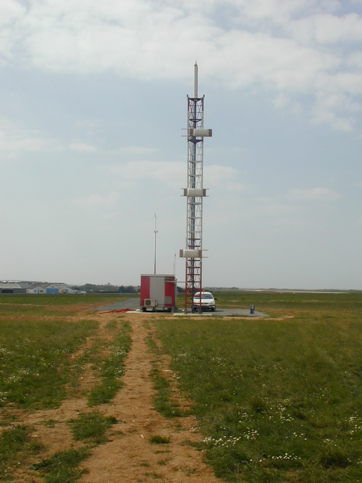
A tower beside the runway that projects the correct descent angle using ground reflection.
- Band
- UHF (329-335 MHz)
- Gain
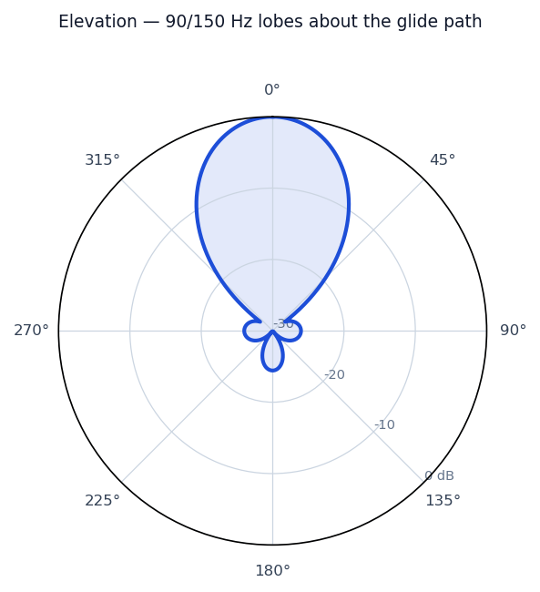
- Shaped vertical lobes (image-antenna)
- Polarization
- Horizontal
Photos
Radiation / wave patterns
New to these diagrams? How to read a radiation pattern →
How & why it works
The glideslope supplies the vertical half of an ILS approach. A mast beside the touchdown zone carries two or three UHF antennas at carefully chosen heights and, cleverly, uses the flat ground in front as part of the antenna: the direct and ground-reflected waves combine to place a 90 Hz-dominant lobe above the desired path and a 150 Hz-dominant lobe below it. Where they balance—typically a 3-degree descent—the aircraft sits on the glide path, and any departure tips the receiver's needle up or down. Because it relies on ground reflection, glideslope siting and the surrounding terrain are critical.
Real-world uses
Vertical guidance of the ILS precision approach; paired automatically with the localizer.