ILS Localizer Array
Aviation & Air-Traffic-Control Antennas Array Navigation VHF Aviation
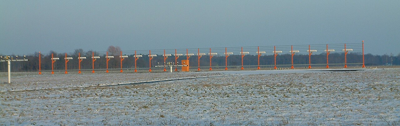
A wide row of antennas past the runway end that defines the approach centerline.
- Band
- VHF (108-112 MHz)
- Gain
- Directional along the runway axis
- Polarization
- Horizontal
Photos
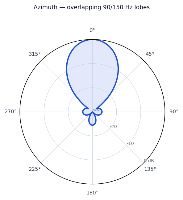
Radiation / wave patterns
New to these diagrams? How to read a radiation pattern →
How & why it works
The localizer gives an aircraft left/right guidance onto the runway centerline. A long horizontal row of paired directional antennas—mounted beyond the far end of the runway—radiates a VHF carrier modulated with two tones, 90 Hz favouring one side of the centerline and 150 Hz the other. Exactly on centerline the two tones arrive equally; off to one side one tone dominates, and the aircraft receiver turns that imbalance into a left/right needle deflection. The array's width sets how sharply the two patterns overlap, which controls the precision of the course.
Real-world uses
Lateral guidance of the ILS precision approach used in low visibility at airports like Calgary.