Small Transmitting (Magnetic) Loop
Loop Antennas HF Portable 🔧 Buildable at home
A compact tuned loop, far smaller than a wavelength, with sharp tuning and high efficiency.
- Band
- HF (typically 80-10 m)
- Gain
- ~ -3 to +1 dBi (size dependent)
- Polarization
- Linear (plane of the loop)
Photos
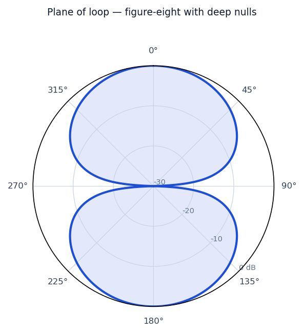
Radiation / wave patterns
New to these diagrams? How to read a radiation pattern →
How & why it works
A small transmitting loop is a single turn of large-diameter tubing, much less than a wavelength around, resonated by a high-voltage vacuum or butterfly capacitor. Because it is electrically small, almost all the stored energy is in the magnetic near field, giving it a very high Q: tuning is razor-sharp and bandwidth is narrow, but a well-built loop can be surprisingly efficient and is far less sensitive to nearby electrical noise than a comparable short whip. Its compact size and deep nulls make it ideal where space is limited.
Real-world uses
Apartment and stealth HF stations, portable operation, and direction finding.
Make one at home
A practical starting point — always trim and check SWR for your exact frequency.
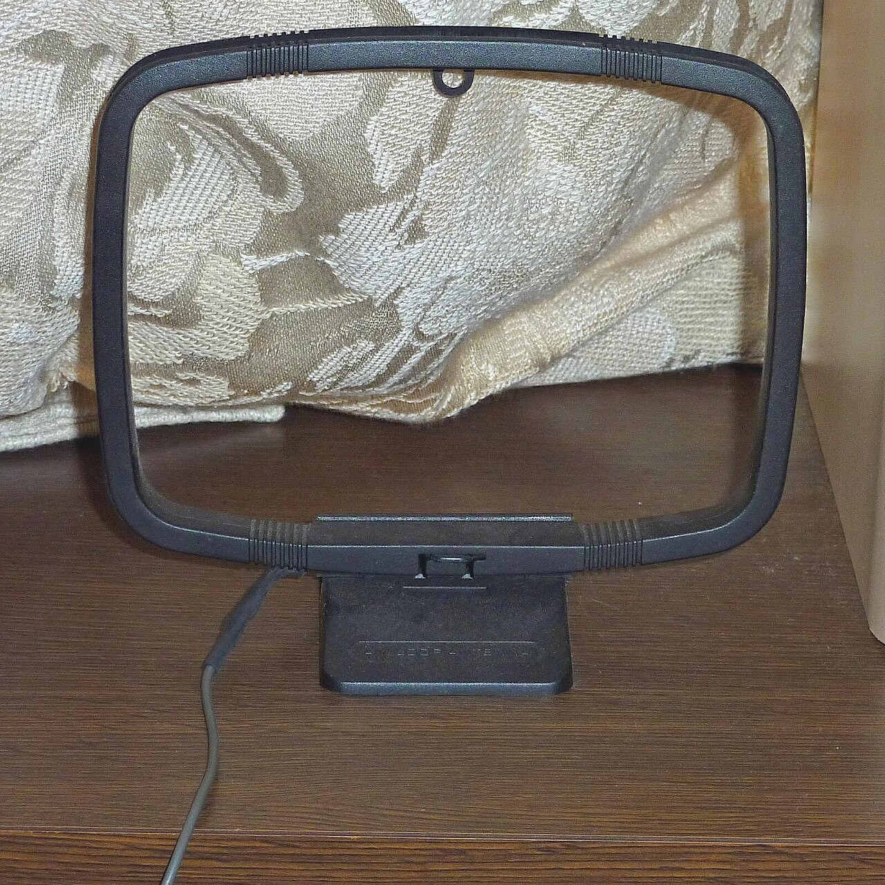
See the finished antenna pictured above ↑.
A small transmitting (magnetic) loop is a compact HF antenna for tight spaces — more involved because of the high-voltage tuning capacitor.
You’ll need
- A loop of large-diameter copper tubing or thick coax braid (circumference ~1/8 wavelength, e.g. ~3 m loop for 20–10 m)
- A wide-spaced or vacuum variable capacitor (the loop develops thousands of volts — ordinary capacitors will arc over)
- A small coupling loop (~1/5 the main loop diameter) for the feed
Build
- Form the main loop and connect its two ends across the variable capacitor.
- Mount the small coupling loop at the bottom, opposite the capacitor, and feed it with coax.
Tune & caution
- Tuning is very sharp — retune the capacitor for even small frequency changes.
- Do not touch the loop or capacitor while transmitting — the RF voltage is dangerous even at modest power. Tune at low power first.
Safety
- Keep antennas well clear of power lines — never put one where it could fall onto or contact mains wiring.
- Don’t transmit while anyone is close to the antenna; mind RF-exposure limits and your local licensing rules.
- Ground masts and use coax surge protection where appropriate.
- Cutting/soldering: eye protection and a ventilated space.