Microstrip Patch
Microstrip & Printed Antennas Microwave UHF
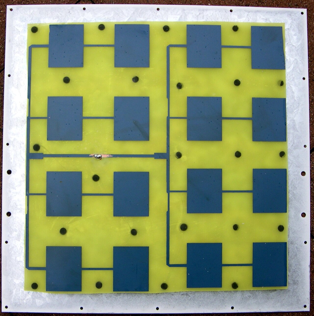
A flat metal patch printed on a dielectric board that radiates broadside.
- Band
- UHF to SHF (microwave)
- Gain
- ~6-8 dBi (single element)
- Polarization
- Linear or circular (feed dependent)
Photos
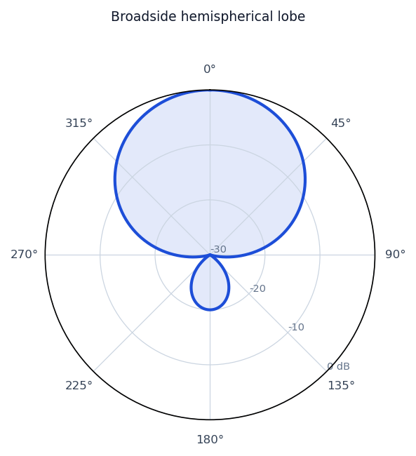
Radiation / wave patterns
New to these diagrams? How to read a radiation pattern →
How & why it works
A patch antenna is a metal rectangle (often a half-wavelength on a side in the dielectric) printed over a ground plane on a circuit board. The patch and ground form a resonant cavity whose fringing fields at two opposite edges do the radiating, sending a beam broadside—straight up off the board. Being flat, light, cheap to mass-produce, and easy to integrate with circuitry, patches are everywhere in modern wireless, and feeding them appropriately can yield linear or circular polarization.
Real-world uses
GPS receivers, Wi-Fi and cellular devices, RFID readers, and phased-array building blocks.