VOR Navigation Antenna
Aviation & Air-Traffic-Control Antennas Navigation VHF Aviation
A ground beacon whose circular antenna array lets aircraft read their bearing from the station.
- Band
- VHF (108-118 MHz)
- Gain
- Low (omnidirectional by design)
- Polarization
- Horizontal
Photos

Radiation / wave patterns
New to these diagrams? How to read a radiation pattern →
How & why it works
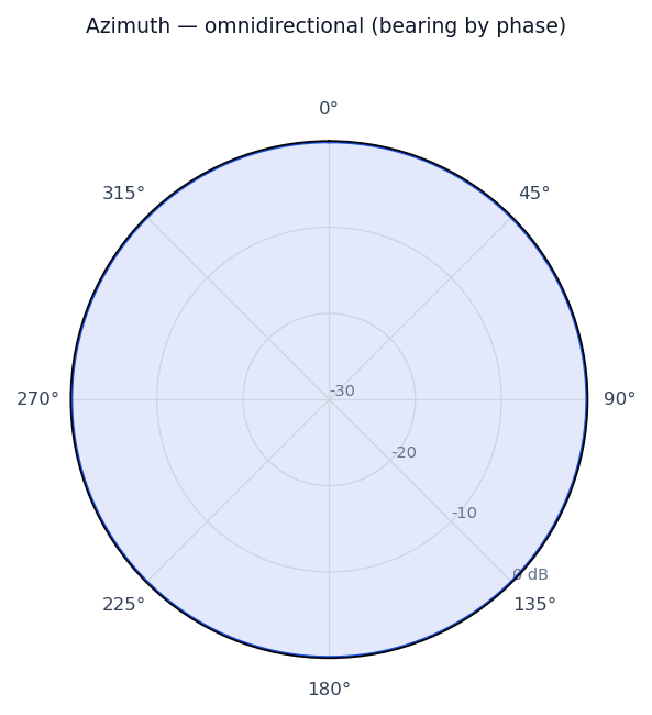
A VHF Omnidirectional Range station tells an aircraft what radial (bearing) it is on. The ground antenna radiates one reference signal equally in all directions and a second signal whose phase rotates around the compass—classically by electronically spinning the pattern of a ring of antennas (a Doppler VOR uses a wide circle of elements switched in sequence to synthesize that rotation). The aircraft simply measures the phase difference between the steady reference and the rotating signal; that difference equals its bearing from the station, the same from any direction, which is why the ground array is circular and the coverage omnidirectional.
Real-world uses
En-route and terminal radio navigation; defining airways and approaches worldwide.